
Installing your modules

This page shows the use of the 3D printed boxes, the designs for which are available to download from the downloads page.
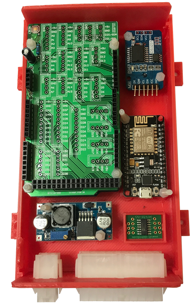
If using “off the shelf” boxes then you should look to mount the modules securely and in a logical fashion. As an example, for both the Arduino and the NodeMCU modules it makes life simpler if you can plug a cable into their respective USB ports for flashing firmware.
I use M3 Nylon nuts and bolts (cheesehead) to secure the modules. This ensures that there is no danger of a nut shorting any of the tracks on the modules. They’re also very easy to cut to length with wire cutters so buy long bolts (30mm).
Order of assembly
It doesn’t matter in what order you install the modules. With the 3D printed box the back panel needs to be installed at the same time as the Arduino. The two are interlocked and it’s not possible to install the back panel once the Arduino is in place.
Assuming you are using the Wingoneer I/O Extension board, use this guide to assembling the board before inserting the Arduino Mega 2560.
The RTC module may require modification prior to installing. Please make sure you read and understand this page detailing the modification.
Fitting each component
The best method of fixing the components in place is to use the provided holes in each module. With the exception of the RTC module and the heater control PCB the modules have holes in suitable for M3 bolts to pass through. Using nylon bolts and nuts to prevent any short circuits is ideal. Trimming these to length is very easy so sourcing long bolts is a good idea. M3 x 30mm bolts are ideal as they can be used for all positions.
The RTC module is drilled with 2mm holes. Either drill the holes out to 3mm or use M2 nylon bolts/nuts. M2.5 will also fit albeit it a very tight fit.
Once all modules are installed, the next step is to add the interconnecting wires and to calibrate the power supply.